
A setup for half-scale slab shear experiments
Last week, I describe the general ideas behind testing a slab with just one steel plate while in reality cars and trucks in many different varieties are loading the structure. I’ll now be going into detail on a few particularities in the setup. As with most of my blog posts, I *try* to write it in such a way that anyone even slightly interested in my work could follow. If you’re a structural engineer/researcher and you want a solid background on my experiments, you can check out my research page or get in touch with me – I’d love to share and exchange ideas (one of my reasons for blogging, that is).
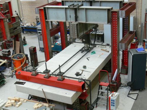
In this post, I’ll write about the test setup which we used in our first series of experiments. 30 specimens were tested in this setup, and in total almost 130 experiments were done in this setup. Here’s how it looks like:
Now there are a few things that I would like to point out in here:
1. The specimen
The concrete slab we test is half-scale of a sold slab bridge. That means that we are looking at a span length of 3,6m and a depth of 30cm. If you’d like to read up on how we make these specimens, here’s a picture-heavy post about the slabs.
2. The frame
It’s steel – we need a whole steel frame around the load to actually apply the load that can destroy the concrete.
3. The load itself
We increase the load level by using a hydraulic jack, connected to the steel plates which are used to model the tire contact area. Here’s how it looks like from close by:
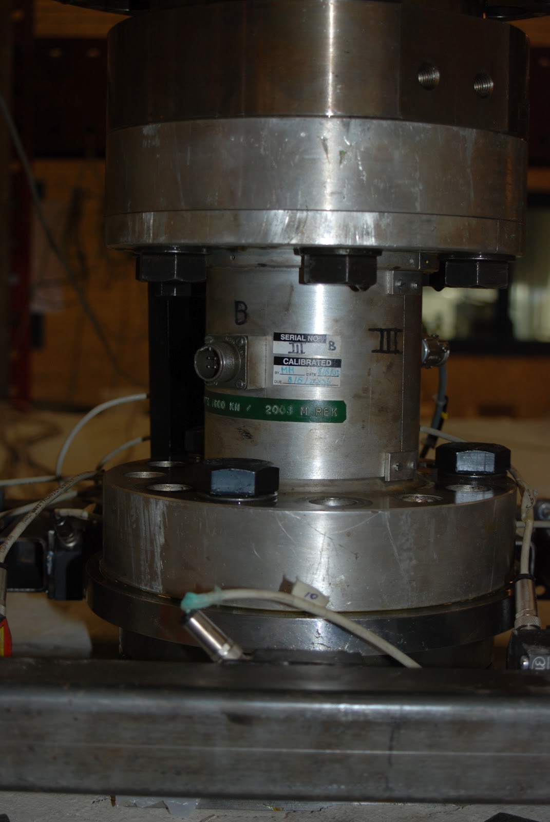
Some researchers have studied the differences between steel plat and rubber pouches filled with water (more like a real tire), to study the difference in an experimental setup. We’ve opted for the standard solution of steel plates – it gives results at the safe side.
4. The support
Since a concrete slab is not perfectly straight, we need an interface, a buffer layer to smooth it all out. We’ve used a layer of felt and a layer of plywood:
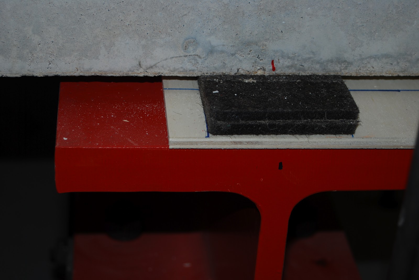
However, for our colleagues who are using complex computer models (non-linear finite element calculations) to simulate the behavior of the slab during the tests, our choice for felt seems to be quite an obstacle. By now, we’ve been testing and squeezing the felt in many different ways, but it turns out to be a difficult material to model.
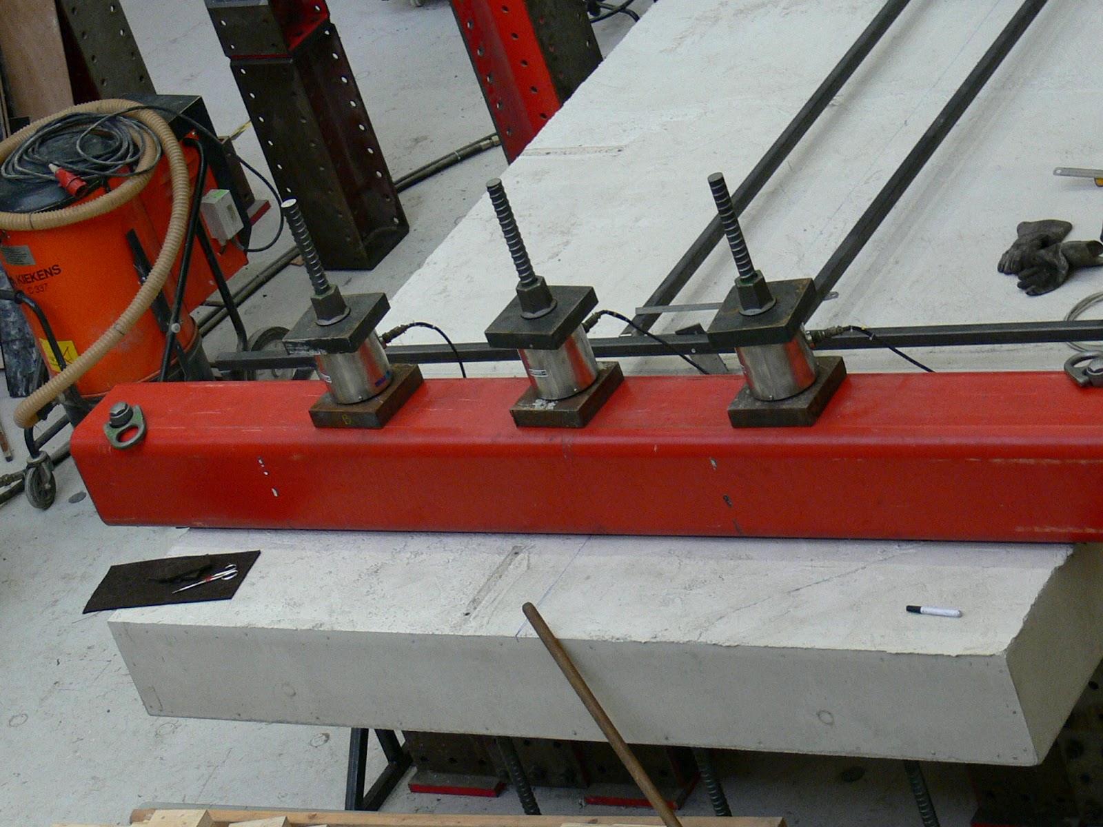
5. The “continuous” support
A real bridge has more than two supports, and that means that the intermediate supports will have a moment at the location of the support. We’ve used prestressing bars, tied to the strong floor of the laboratory to hold back the rotation of the slab over the support – and thus creating a moment there were we need it. In the picture below, there are the ends of the 3 bars, all with a load cell to measure the force in the bar, and the red box beam which distributes the load over the width of the specimen. Also, note that underneath the concrete specimen, you can see that the prestressing bars keep going down – in fact, they go down through the strong floor all the way to the basement.
6. The measurements
Look at the smaller black lines you see over the concrete slab, parallel to the support and over the span length. Those are parts of the measurement frame: we use lasers to measure the displacements at several positions, to know how the slab reacts to the load. To hold the lasers into their fixed position, they are mounted on these smaller steel frames.
That basically sums up the most important elements of my first test setup. For our second series of tests, we had to make a few changes, but I’ll get back to that in another post.